
Ever since my oldest brother made a set of speakers I knew that one day it would be my turn. His were big, heavy (from memory, approximately half the weight of an arcade cabinet), had three channels, constructed from chipboard, had a lame wood-effect peel & stick laminate on the sides and top, a hessian finish front, and were designed according to some 1980's golden ratio rule. They were however awesome, and have survived 30 years so far. His speakers still get dragged out to rock New Years Eve and other family parties. You can dance on them; they are indestructible.
My brother was single at the time he built his, and was operating on a student budget. I however, that many years later, had to consider the wife-friendlyness of any construction in order to continue the legacy. So I knew I would have to invest more effort in the area of aesthetics, but at the same time wasn't prepared to build something that didn't sound good. So, for a couple of years prior to building, on and off, I investigated and researched the current state of self-build enclosure design.
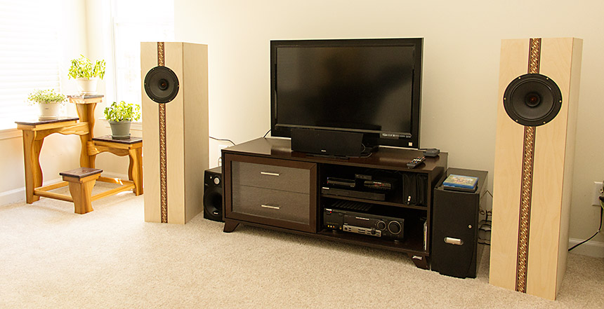
Below is the result of my efforts, and further down I'll explain some of the decision, steps involved, and challenges. This isn't a tutorial, I'm simply not qualified as this was my first (and likely only) set of speaker enclosures that I'll build.
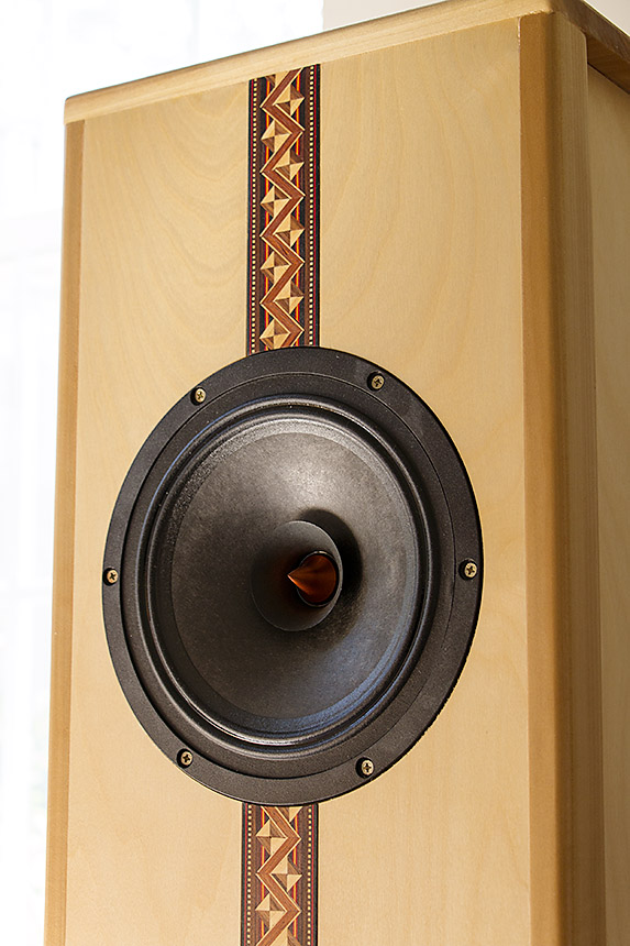
First, allow me explain why they look like a guitar. It wasn't that I'm a guitar fan and had set out to fashion them after the instrument, it just turned out that way. I realized that without some feature to break up the front, they would look fairly bland. I quickly decided that a strip of inlay would do the trick and started hunting online for possibilities. For the relatively large area of the front of the enclosure, it couldn't just be a skinny strip of purple heart. It needed to be something reasonably wide, and that feature was central to the design from early on.
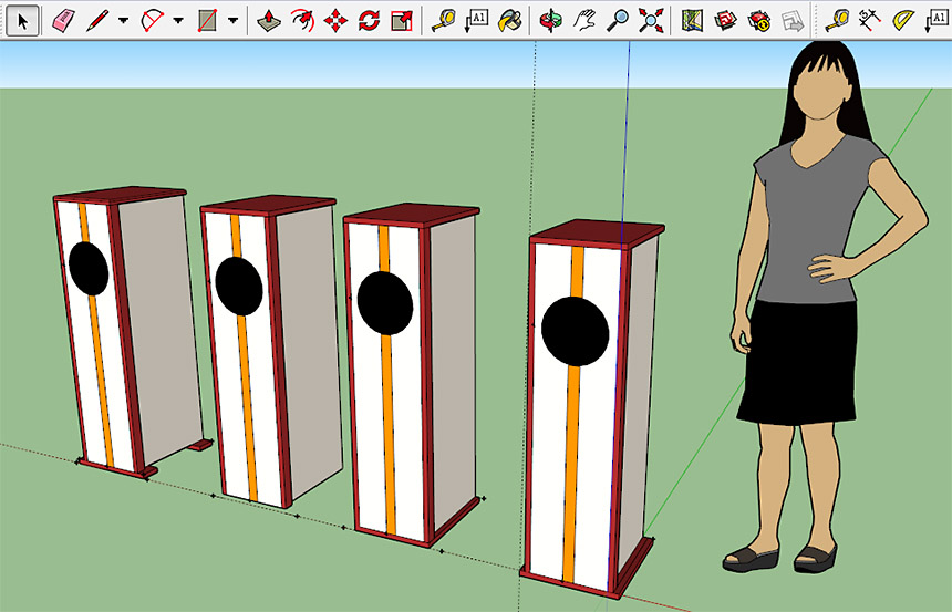
Above, using SketchUp I rendered several different configurations (of feet in this case), and had also gone through several versions of inlay layout. One where the inlay runs from the bottom and stops at the driver (which looked to me a bit like a popsicle), another where a much shorter inlay runs at 45 degrees from the bottom center off to one side and just visually cuts a corner. I ended up keeping it simple, and running it the full height. From a materials perspective however, this was the most expensive choice.
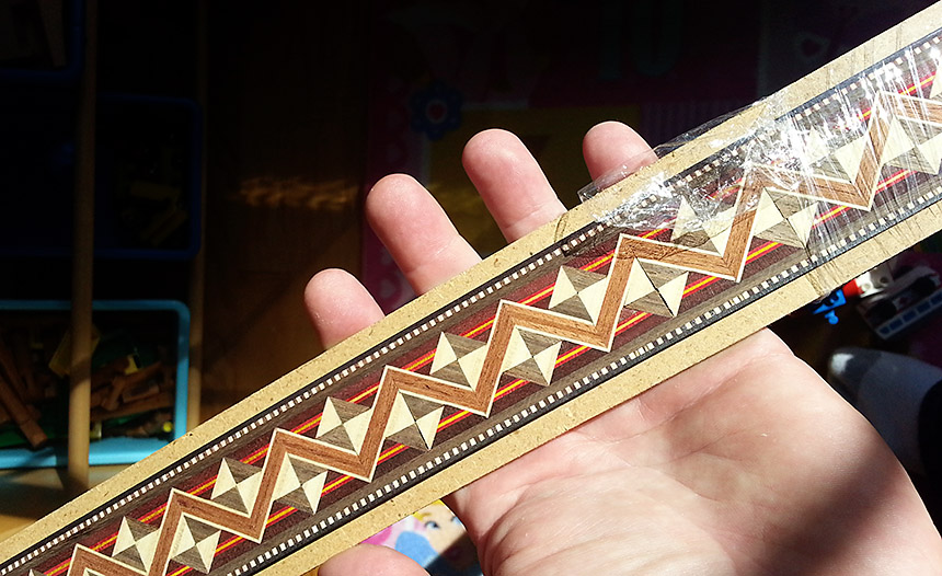
Inlay can get costly, especially wide ones. The strips I purchased claimed to be sourced from French block stock, approximately 100 years old, that had only recently been cut into inlay strips for sale. 100 years old, or 2 years old... doesn't matter because they are still very attractive.
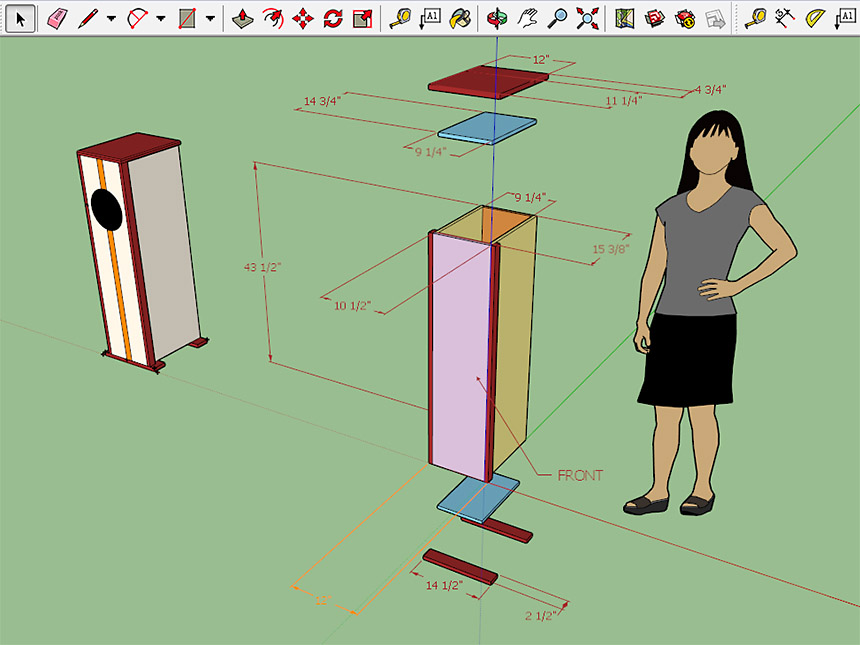
This SketchUp shows the exploded view of the design from which I made my cuts. A few things to note about why I chose to box it this way:
- All fixings were to be hidden from the top, sides, and front; the only ones allowed to show are on the rear panel.
- Therefore, the front panel is made wider to cover the otherwise exposed side-panel edges
- The side panels are made wider to cover the otherwise exposed rear-panel edges
- The top panel (shown here in blue, forming the top of the acoustic box) has its edges covered by side, front and rear panels
- The bottom panel (again in blue) follows the same pattern as the top panel
- The red wood is all decorational. Two strips down the front sides hide the front panel edges, and a lid hides all exposed side, top, and front panel edges. Ultimately material and staining decisions lead me to a wood that wasn't actually red.
- The feet I did make but decided late in the project to exclude them. Oddly enough the drawings look better with feet than the actual enclosures did.
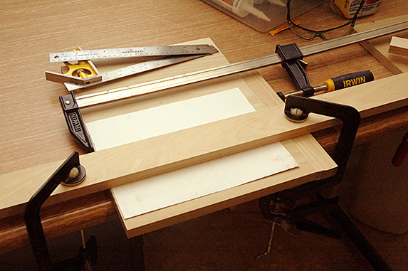
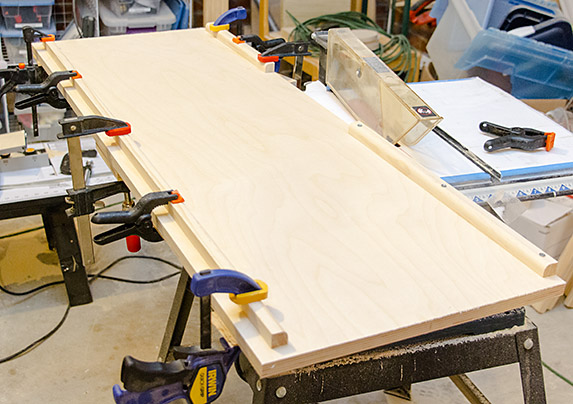
Clamps above configured to route the wide groove that holds the inlay strip. It took several passes.
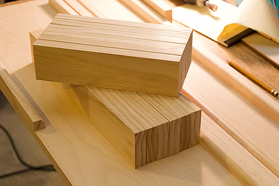
For many people who build enclosures, the material of choice is 3/4" Baltic Birch Ply (13 layers). It's dimensionally stable (stiff), much stronger than MDF or chipboard, and unlike other plys it has little to no voids in the inner layers that can cause resonance issues. The front and back surfaces are cabinet grade (at least one side is, sometimes both) and looks fairly decent with just a layer of varnish. I chose poplar for the side trims and top surface because it's a wonderfully easy wood to work with, and it changes color over several years from a weird greenish purple stripe to a nice warm golden color.
I should mention that the dimensions for an enclosure are fairly critical from the perspective of sounding good, and that the optimum configuration has to be determined around the driver or drivers being used. In other words, step one in building an enclosure is to choose the driver(s). Steps 2 to 200 are a bunch of complicated calculations that take some 6 or more metrics from the driver specifications and using width height & depth ratios, volumes, driver position, port diameter and depth, distance to wall, material thickness, bracing displacement etc, you finally get the internal measurements of the enclosure that will best support the driver(s).
I investigated multiple driver combinations over many months. Each had advantages and disadvantages. I ended up reducing cost and complexity by choosing to use a modern full-range driver. Having to cut just one centered recessed hole out of each panel was far less scary too. Full range drivers do not require any crossover (the circuit in most speakers that divides the signal into frequency bands so that each driver gets just the right range based on its capability). They also provide superb clarity/imaging as the entire audio spectrum is emanating from the same location at the front of the enclosure. Thus you are not forced to stay 8 feet away from them to allow proper integration of the sound that a three-driver solution might require.
The driver I settled on are Dayton Audio PS220-8, a high sensitivity, high excursion 8" Kevlar reinforced cone driver with neodymium magnet. Rated at 40 Watts, 8 Ohms and a frequency response of 40-25,000Hz they also look fairly attractive with the copper cap. These were about $130 each.
Having selected the driver, I searched for enclosure plans. I wasn't about to spend weeks building something that nobody had ever tried (I know my limits) so I was pleased to find the 'Singularity' design by Curt Campbell and Wayne Wendel. These guys have built many enclosures. Based on their approximate measurements as guides, and following their port configuration exactly, using an enclosure design spreadsheet I was able to re-produce their calculations to a more precise volume. This allowed be to tweak my enclosure dimensions to provide enough excess volume to displace again with the bracing and stops I needed to add to make my box fit together.
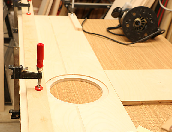
This project presented many challenges. Attempting to accurately cut such large panels using just a portable table saw was futile. So each edge of each panel (repeat for a total of 48 edges) had to be rough cut with the table saw, then finish-cut with a router which ran along a guide I clamped to the wood at precisely the right point.
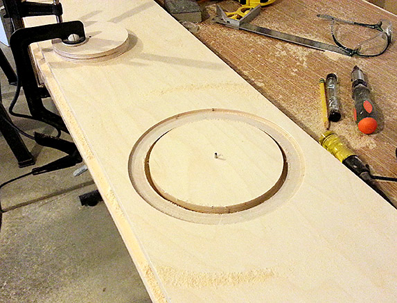
I cut holes (recesses first), then a smaller circle inside for the drivers using the router and a hole-cutting jig. Double sided sticky tape kept the inner circle holding the guide pin in place during the full-depth cut.
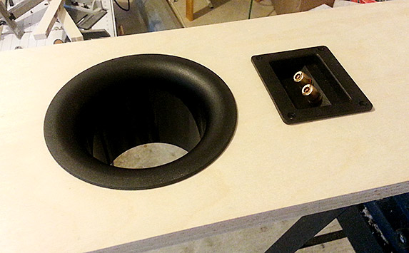
Holes for the rear port and connection terminals cut, and tested for fitting.
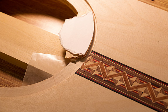
Here I constructed a small jig that allowed me to support the inlay as I cut, with a box cutter, a curved edge where it meets the driver. Without that wood and white card jig, the inlay would have fractured along the cut. I then finished this with a Dremel rotary tool sander. The project required many such little jigs and templates to be custom-built out of scraps as I went along.
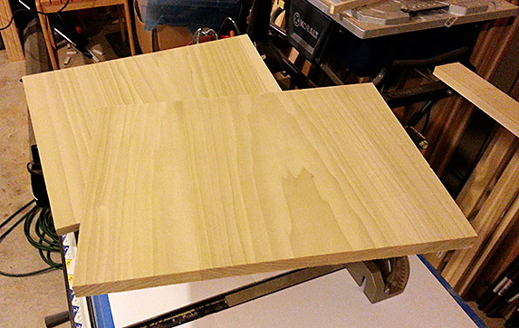
The top surfaces, made from two glued planks of poplar, they started out a greenish color.
Side pieces had stops added, the recessed ones on the left are for the back panel to sit against, and the flush ones on the right attach to the front. The two at the front form a gap where the driver needed clearance. All of these pieces displace internal volume and allowances had to be made for them in the calculations prior to cutting the panels.
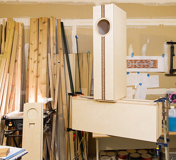
You can never have enough clamps, and you will never have a clamp large enough. With the enclosure height at around 3 ft 9" clamping in some directions just wasn't possible. When gluing the front onto the frame I had to stack one enclosure on top of another to make a gravity clamp.
Cross bracing is required to stop the enclosure flexing with the sound pressure from the drivers. The enclosure is supposed to be rigid. Here, they are cut to fit inside, and touch either front to back or side to side.
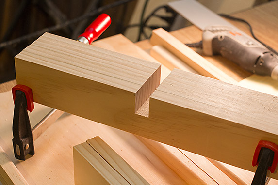
Dados cut into the pieces to allow them to form crosses. There are simpler solutions for bracing, but I liked this configuration best.
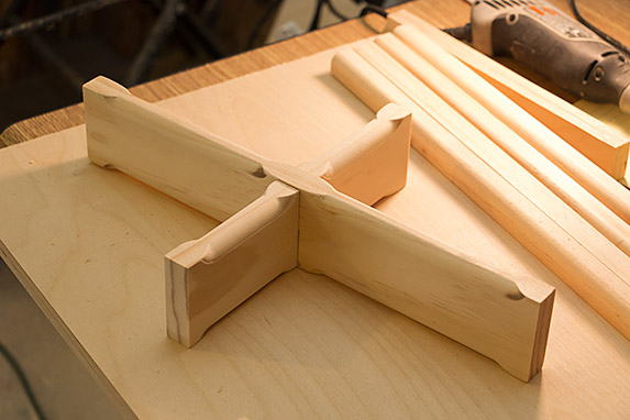
Crossbrace prior to sanding. The roundover routing was done to remove sharp 90 degree edges which are generally bad inside the enclosure as they can set up unwanted sound reflections. You'll notice the internal stops were all routed too, for the same reason.
This is the step at which many self-build enclosure projects end: The initial sound tests. From an audio perspective, the enclosures are complete: sealed (excluding the rear port), rigid, and wired up with drivers. The problem is, they just sound too good for you to want to take them off the amp again and back to the workshop for finishing - something that could take several days. I kept them hooked-up for about a week and then forced myself to complete them.
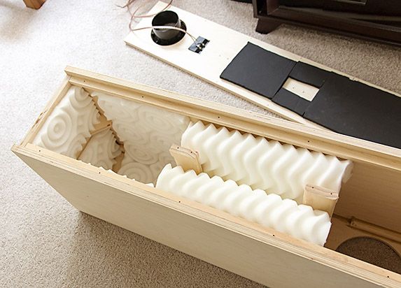
This design of enclosure requires acoustic stuffing. I used a mixture of sound-absorbing foam (the black stuff) on surfaces directly behind the driver as a reflection suppressant, and foam from a mattress topper (the white stuff) which helps reduce standing waves. The black stuff displaces (some) internal volume, the white doesn't to any practical extent. You can also see on the floor of the enclosure one of the little triangle supports that helped me maintain 90 degree box when gluing it up.
One thing to note about the white foam: It is flammable, and toxic when burning. So it shouldn't be anywhere near the driver coil (which, in theory could achieve ignition temperature if DC were applied to the speaker for many seconds - a condition that is rarely possible with modern amps and would destroy the driver with some nice smoke effects within seconds). I considered not using it for a while before deciding that unattended fire ignition risks were extremely low, and the enclosure would likely survive/contain that fire. I have not however tested that theory.
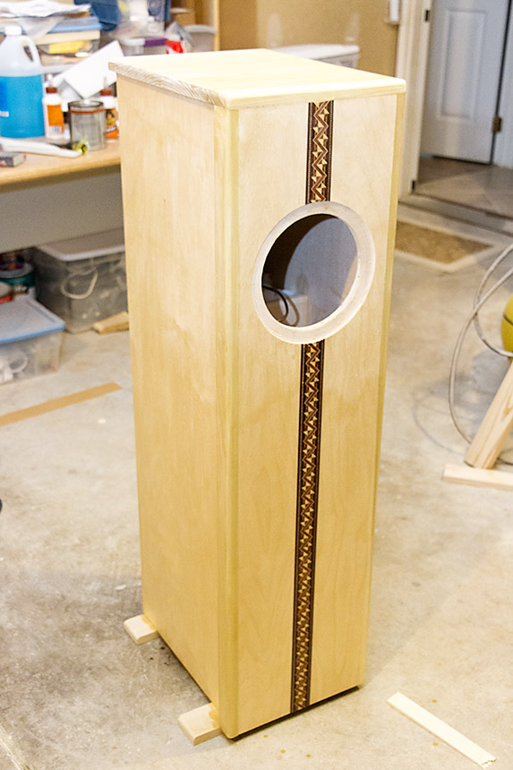
Drivers removed again. Side trims added, and the top. I started with two coats of Clear Glass Polyurethane from an Aerosol can. Clear because even though I wanted to finish with a Satin, you want to avoid multiple coats of satin otherwise it can get misty. Aerosol because the dyes in the inlay might bleed from having a pad or brush dragged across it. For the sides I just used a foam brush and a tin of the same stuff. It had maybe 4 coats in total, ending with a coat of Satin.
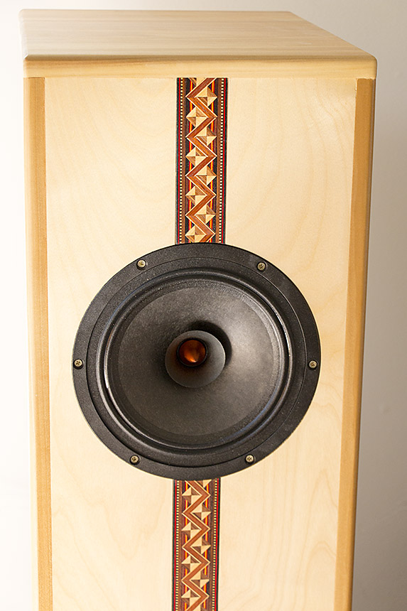
So this is what I ended up with. A few months afterwards I ended up adding a notch filter which is housed inside a small plastic box in each enclosure. It's a simple circuit: a resistor (12 Ohm), capacitor (9uF) and air core inductor (0.2mF) that takes about 4dB off a 3.6Khz peak where these drivers appear to be overly bright. The filter flattens the response curve of the speaker (not to flat-flat, but to less-bumpy), and now they sound even more wonderful. There's a fair amount of confusion online about the nature of a simple RLC notch filter. The three components don't have polarity and should be wired in parallel with each other. The entire RLC network should then be wired in series with the driver. Buy high quality components, they aren't particularly expensive.
This project was fun. I learned a great deal, and I get to enjoy the result most evenings.